Lernfeld 9

Überprüfung einer elektronischen Schaltung mit automatisierter Messtechnik

Das kann man realisieren z.B. mit
Verwendung einer Messbox (z.B: Labjack) und eine Auswertungssoftware z.B.
Profilab

Einfacher Fall: Überprüfung eines Sensorwertes, hier eine Temperatur, auf zu niedrig, richtig, zu hoch:

Ein weiteres Beispiel zur Erfassung eines Füllstandsensors:

oder LabView zum automatisiertem  Testen von Platinen

In Lernfeld 11 wird auf ein Projekt eingegangen, wo eine Messbox entwickelt wird mit einem Arduino µController. Das entspricht einer Erweiterung dieser Unterrichtsinhalte.

Einparkhilfe mit µC umgesetzt

Das Lernortkooperationsprojekt (Was für ein Wort…) Einparkhilfe aus dem 2. Ausbildungsjahr kann hier nochmals aufgegriffen werden. Allerdings nutzen wir nun die programmierbare Elektronik, sprich µC.
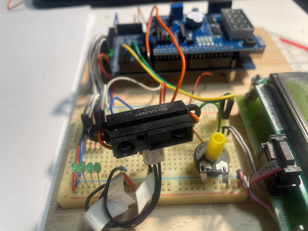
Der verwendete Sensor soll zuerst einmal der gleiche sein. Es ist der SHARP GP2D12 10 – 80 cm) siehe Pflichtenheft , der eine analoge Spannung entsprechend dem Abstand liefert. Die Anzeigeelemente können vielseitig gewählt werden, sei es optische oder akustische Signale, natürlich auch Anzeigeelemente wie LC-Display, 7Seg. Anzeige, LED Band.

Entsprechend sieht das Pflichtenheft aus:

Umsetzungshilfen:

Der SHARP Sensor auf einem kleinen Entwicklungsbord mit Multi-Funktion-Shield (ca. 3 bis 5€) und Arduino MEGA Controller mit kleinem Steckboard und IIC-LC Display.

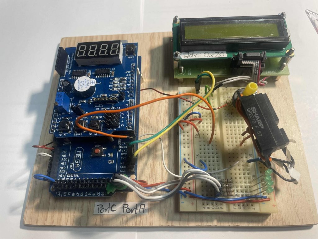
Hier ein Einstieg in die Erfassung des Messwertes mit einer gemultiplexten 7 Seg Anzeige auf dem MF-shield:

/* *******************************************************************************
|  CLASS:       Arduino UNO und MEGA
|  Compiler:  Arduino
|  PROGRAM:     SHARPSensor4x7Seg_Neumaier.ino   ->ino = Arduino Source code 
|  AUTHOR:      Gerhard Neumaier
|  DATE:        1Jan16
|  DESCRIPTION: Multi-funktion board 
       
|  REQUIREMENTS:  Arduino UNO Multi-funktion board  SHARP Sensor GP2Y0A21Y   10-80cm
                  
|  NOTES: Ein komplettes Programm, Anzeige flimmert viele Messwerte pro Zeiteinheit machen 
Anzeige unleserlich an letzter Stelle, Ein delay hilft nicht, denn dann wird der Multiplexeffekt sichtbar. Die Anzeige speichert den letzten Wert leider nicht. Die Messwertaufarbeitung im Treiber dauert zu lange
Ausweg: Auf die Library für den SHARP verzichten, dann muss man die Linearisierung selbst machen.
|  Aufgaben:   Linearisierung per Software, Library SHARP Herausnehmen
               oder
Die Ansteuerung der 7 Seg- Anzeige in einen Timerinterrupt legen. Diese Routine unterbricht die Messwertberechnung kurz. Das bemerkt man aber nicht.

|  History:   
*******************************************************************************/
//Wie immer: vor dem Test den Ordner: SharpIR in den libraries Ordner der ARDUINO IDE kopieren
#include <SharpIR.h>
//Quelle: http://playground.arduino.cc/Main/SharpIR
#define ir A10
#define model 1080
// ir: the pin where your sensor is attached
// model: an int that determines your sensor:  1080 for GP2Y0A21Y   10-80cm
//                                             20150 for GP2Y0A02Y   20 - 150 cm
//        (working distance range according to the datasheets)
/*
## GP2Y0A21YK
| Volt | Distance |
| 2,6  | 10 |
| 2,1  | 12 |
| 1,85 | 14 |
| 1,65 | 15 |
| 1,5  | 18 |
| 1,39 | 20 |
| 1,15 | 25 |
| 0,98 | 30 |
| 0,85 | 35 |
| 0,75 | 40 |
| 0,67 | 45 |
| 0,61 | 50 |
| 0,59 | 55 |
| 0,55 | 60 |
| 0,5  | 65 |
| 0,48 | 70 |
| 0,45 | 75 |
| 0,42 | 80 |
Using MS Excel, we can found folowing formula (For distance > 10cm) :
Distance = 29.988 X POW(Volt , -1.173)
*/
SharpIR sharp(ir, 5, 60, model);//ir: A0, model: 1080 oben definiert Hinweis: !!Vier Uebergabewerte!!
// ir: the pin where your sensor is attached
// 25: the number of readings the library will make before calculating a mean distance
// 93: the difference between two consecutive measurements to be taken as valid
//consecutive measurements: Aufeinanderfolgende Messwerte
// model: an int that determines your sensor:  1080 for GP2Y0A21Y
//                                            20150 for GP2Y0A02Y
//                                            (working distance range 
/* Define shift register pins used for seven segment display */
#define LATCH_DIO  4  //LATCH_DIO has Pin number 4
#define CLK_DIO    7
#define DATA_DIO   8

/* Segment byte maps for numbers 0 to 9 */
const byte SEGMENT_MAP[] = {0xC0, 0xF9, 0xA4, 0xB0, 0x99, 0x92, 0x82, 0xF8, 0X80, 0X90};
/* Byte maps to select digit 1 to 4 */
const byte SEGMENT_SELECT[] = {0xF1, 0xF2, 0xF4, 0xF8};

void setup ()
{
  /* Set DIO pins to outputs */
  pinMode(LATCH_DIO, OUTPUT);  //Pins vorgegeben durch MFShield Ansteuerung 4x7Seg Anzeige
  pinMode(CLK_DIO, OUTPUT);
  pinMode(DATA_DIO, OUTPUT);
  //SHARP Sensor:
    pinMode (ir, INPUT);
}

/* Main program */
void loop()
{
   int dis=sharp.distance();  // this returns the distance to the object you're measuring
  //delay(50);
  /* Update the display with the current counter value */
  WriteNumber(dis); //you will now call the function WriteNumber(Count);
} 

//
/* Write a decimal number between 0 and 9999 to the display */
void WriteNumber(int num)
{
  int thousand, hundred, ten, one; //local varaible
 // breakdown number into columns
 thousand = num/1000;                               //examples: 2345/1000=2
 hundred = (num-(thousand*1000))/100;               //2345-2000=345/100=3
 ten = (num-((thousand*1000)+(hundred*100)))/10;    //2345-2000-300=45/10=4
 one = num-((thousand*1000)+(hundred*100)+(ten*10));//2345-2000-300-40=5
 
//  WriteNumberToSegment(0 ,thousand );     //you will now call the function  WriteNumberToSegment(0 , Number / 1000);
//  WriteNumberToSegment(1 , hundred);
  WriteNumberToSegment(2 , ten);
  WriteNumberToSegment(3 , one );
}


/* Wite a ecimal number between 0 and 9 to one of the 4 digits of the display */
void WriteNumberToSegment(byte Segment, byte Value)
{
  digitalWrite(LATCH_DIO, LOW);       //Shift register 74xx595: https://www.arduino.cc/en/Tutorial/ShiftOut
  shiftOut(DATA_DIO, CLK_DIO, MSBFIRST, SEGMENT_MAP[Value]);  //look by help -> referenz ->shift out
  shiftOut(DATA_DIO, CLK_DIO, MSBFIRST, SEGMENT_SELECT[Segment] );
  digitalWrite(LATCH_DIO, HIGH);
  //delay(1);  //you can see the multiplex effect  flimmering display
}
/* *******************************************************************************
|  CLASS:       Arduino UNO und MEGA
|  Compiler:  Arduino
|  PROGRAM:     SHARPSensor4x7Seg_Neumaier.ino   ->ino = Arduino Source code 
|  AUTHOR:      Gerhard Neumaier
|  DATE:        1Jan16 24Jan26
|  DESCRIPTION: Multi-funktion board 
       
|  REQUIREMENTS:  Arduino UNO Multi-funktion board  SHARP Sensor GP2Y0A21Y   10-80cm Sensor an A10 angeschlossen
|  NOTES: Ein komplettes Programm. Ausgabe 7Seg Anzeige in Timer1ISR gelegt alle 10msec.Somit flimmerfreie Anzeige stabile Werte.  Nur die letzten zwei Stellen werden benutzt. Der Messwert wird von der loop nur jede 0,5 sec geliefert. Vorteile: Sensor Software hat die notwendige Zeit zum rechnen ca. 50-70msec. Letzte Ziffer bleibt stabil.
       
|  Aufgaben:   Nun die Einparkhilfe weiter programmieren: verschiedene Töne durch den Summer erzeugen. Blinkende LED bei geringem Abstand. DUO LED einbinden usw
               Programm aufräumen und dokumentieren.   
|  History:    3Jan2016  Jan26
*******************************************************************************/
//Wie immer: vor dem Test den Ordner: SharpIR in den libraries Ordner der ARDUINO IDE kopieren
#include <SharpIR.h>
#include "TimerOne.h"  //Library vorher in das Verzeichnis libraries kopieren
//Quelle: http://playground.arduino.cc/Main/SharpIR
#define ir A10
#define model 1080
// ir: the pin where your sensor is attached
// model: an int that determines your sensor:  1080 for GP2Y0A21Y   10-80cm
//                                             20150 for GP2Y0A02Y   20 - 150 cm
//        (working distance range according to the datasheets)
/*
## GP2Y0A21YK
| Volt | Distance |
| 2,6  | 10 |
| 2,1  | 12 |
| 1,85 | 14 |
| 1,65 | 15 |
| 1,5  | 18 |
| 1,39 | 20 |
| 1,15 | 25 |
| 0,98 | 30 |
| 0,85 | 35 |
| 0,75 | 40 |
| 0,67 | 45 |
| 0,61 | 50 |
| 0,59 | 55 |
| 0,55 | 60 |
| 0,5  | 65 |
| 0,48 | 70 |
| 0,45 | 75 |
| 0,42 | 80 |
Using MS Excel, we can found folowing formula (For distance > 10cm) :
Distance = 29.988 X POW(Volt , -1.173)
*/
SharpIR sharp(ir, 20, 60, model);//ir: A0, model: 1080 oben definiert Hinweis: !!Vier Uebergabewerte!!
// ir: the pin where your sensor is attached
// 20: the number of readings the library will make before calculating a mean distance
// 60: the difference between two consecutive measurements to be taken as valid
//consecutive measurements: Aufeinanderfolgende Messwerte
// model: an int that determines your sensor:  1080 for GP2Y0A21Y
//                                            20150 for GP2Y0A02Y
//                                            (working distance range 
/* Define shift register pins used for seven segment display */
#define LATCH_DIO  4  //LATCH_DIO has Pin number 4
#define CLK_DIO    7  //This pins are fix for the MultiFunktionShield 7Seg Display
#define DATA_DIO   8

/* Segment byte maps for numbers 0 to 9 */
const byte SEGMENT_MAP[] = {0xC0, 0xF9, 0xA4, 0xB0, 0x99, 0x92, 0x82, 0xF8, 0X80, 0X90};
/* Byte maps to select digit 1 to 4 */
const byte SEGMENT_SELECT[] = {0xF1, 0xF2, 0xF4, 0xF8};
int num;


void setup ()
{
  /* Set DIO pins to outputs */
  pinMode(LATCH_DIO, OUTPUT);
  pinMode(CLK_DIO, OUTPUT);
  pinMode(DATA_DIO, OUTPUT);
  //SHARP Sensor:
    pinMode (ir, INPUT);
Timer1.initialize(10000); //Angabe in mikrosec 10000usec=10msec
Timer1.attachInterrupt(Timer1_ISR);

}

void Timer1_ISR() //Jede 10msec wird diese Funktion aufgerufen
{
/* Write a decimal number between 0 and 9999 to the display */
//void WriteNumber(int num)
//{
  int thousand, hundred, ten, one; //local varaible
 // breakdown number into columns
// thousand = num/1000;                               //examples: 2345/1000=2
// hundred = (num-(thousand*1000))/100;               //2345-2000=345/100=3
 ten = (num-((thousand*1000)+(hundred*100)))/10;    //2345-2000-300=45/10=4
 one = num-((thousand*1000)+(hundred*100)+(ten*10));//2345-2000-300-40=5
 /* or easier when the num 0 to max 99:
  ten = num/10;    //45/10=4
 one =  num-(ten*10); //45-40=5
 */
 // WriteNumberToSegment(0 ,thousand );     //you will now call the function  WriteNumberToSegment(0 , Number / 1000);
 // WriteNumberToSegment(1 , hundred);
  WriteNumberToSegment(2 , ten);
  delay(2);    //Sonst leuchtet Zehnerstelle zu dunkel -> Besser mit Umschaltung ten one arbeiten. 
  //Einmal leuchtet ten im nächsten INT one usw.
  WriteNumberToSegment(3 , one );
//}
 }

 
/* Main program */
void loop()
{   //num=1234; //for test only
   num=sharp.distance();  // this returns the distance to the object you're measuring
   //Variable num will be used in the Timer1ISR
   if (num>=82)
   {num=82;}
    if (num<=9)
   {num=9;}
  delay(500);
  /* Update the display with the current counter value */
  //WriteNumber(dis); //you will now call the function WriteNumber(Count);
} 

//


/* Wite a ecimal number between 0 and 9 to one of the 4 digits of the display */
void WriteNumberToSegment(byte Segment, byte Value)
{
  digitalWrite(LATCH_DIO, LOW);       //Shift register 74xx595: https://www.arduino.cc/en/Tutorial/ShiftOut
  shiftOut(DATA_DIO, CLK_DIO, MSBFIRST, SEGMENT_MAP[Value]);  //look by help -> referenz ->shift out
  shiftOut(DATA_DIO, CLK_DIO, MSBFIRST, SEGMENT_SELECT[Segment] );
  digitalWrite(LATCH_DIO, HIGH);
}


/* Wite a ecimal number between 0 and 9 to one of the 4 digits of the display */
void WriteNumberToSegment(byte Segment, byte Value)
{
  digitalWrite(LATCH_DIO, LOW);       //Shift register 74xx595: https://www.arduino.cc/en/Tutorial/ShiftOut
  shiftOut(DATA_DIO, CLK_DIO, MSBFIRST, SEGMENT_MAP[Value]);  //look by help -> referenz ->shift out
  shiftOut(DATA_DIO, CLK_DIO, MSBFIRST, SEGMENT_SELECT[Segment] );
  digitalWrite(LATCH_DIO, HIGH);
  //delay(1);  //you can see the multiplex effect  flimmering display
}

———————————————————–

Regelungstechnik

Die Umsetzung und Vertiefung dieses interessanten Themas erfolgt mit Simulationssoftware.
Siehe auch den Link im Menue „Simulation“
1. Multisim und MultisimLife(im Browser)    Multism National Instruments
2. Winfact mit dem Modul BORIS                 Winfact Ingenieurbüro Dr.Kahlert

PPT Regelungstechnik mit Winfact:

Grundlagen Regelungstechnik Übersicht über Blocksymbole und Dimensionierung

Ein Skript zum Thema Steuern und Regeln über 62 Seiten. Viele Steuerungsaufgaben und Lösung mit einer SPS LOGO Gegen Ende auch das Thema Regelungstechnik mit den bekannten Reglern